Pearson 10M Sailboat Cradle
Published: 04 January 2012
The marina where my boat is at does not like boat stands and they charge a premium (about $300 per winter) to have a boat stored on stands. I paid the premium last winter but this fall I decided to make a cradle for the boat. The boat's basic specs are 10 meters long - about 33 feet, 11 ft wide, draft of about 6 feet and a empty weight of about 12,000 lbs. The boat is stored with the mast up. The boat yard transports the boat on the cradle with a hydraulic yard cradle trailer. So the cradle frame must be robust. A lightweight cradle frame will not work.
People have asked me why some other marinas prefer cradles and the only reason I can come up with is that for some marinas using cradles improves their efficiency. They can place the boats closer together in storage since narrow hydraulic trailers are used to set the cradle/boat. Also using cradles can use less labor. Once a cradle is made for a particular boat, placing the boat into it's cradle with a travelift is fairly simple, whereas moving stands around, placing the stands and then chaining them together can be some work.
I watched Craigslist and Ebay for cradles that might fit this boat and found nothing that was even close, so I started looking for basic cradles that I could rework. I found one in Sandusky for a lot less than I could purchase the steel. So I drove their with my trailer and picked it up just before the weather really turned cold (highs of about 10 degrees in early November!)
The cradle base I purchased is about 17 feet long and 7 feet wide. I cut off all of the uprights with a plasma cutter and then ground them close to flush with the top of the channel steel framework. The cradle frame is made of 8 inch channel on the outside with a mix of 8 and 6 inch cross members. The existing frame welds were adequate.
But where to place the uprights? At what angle? And how tall?
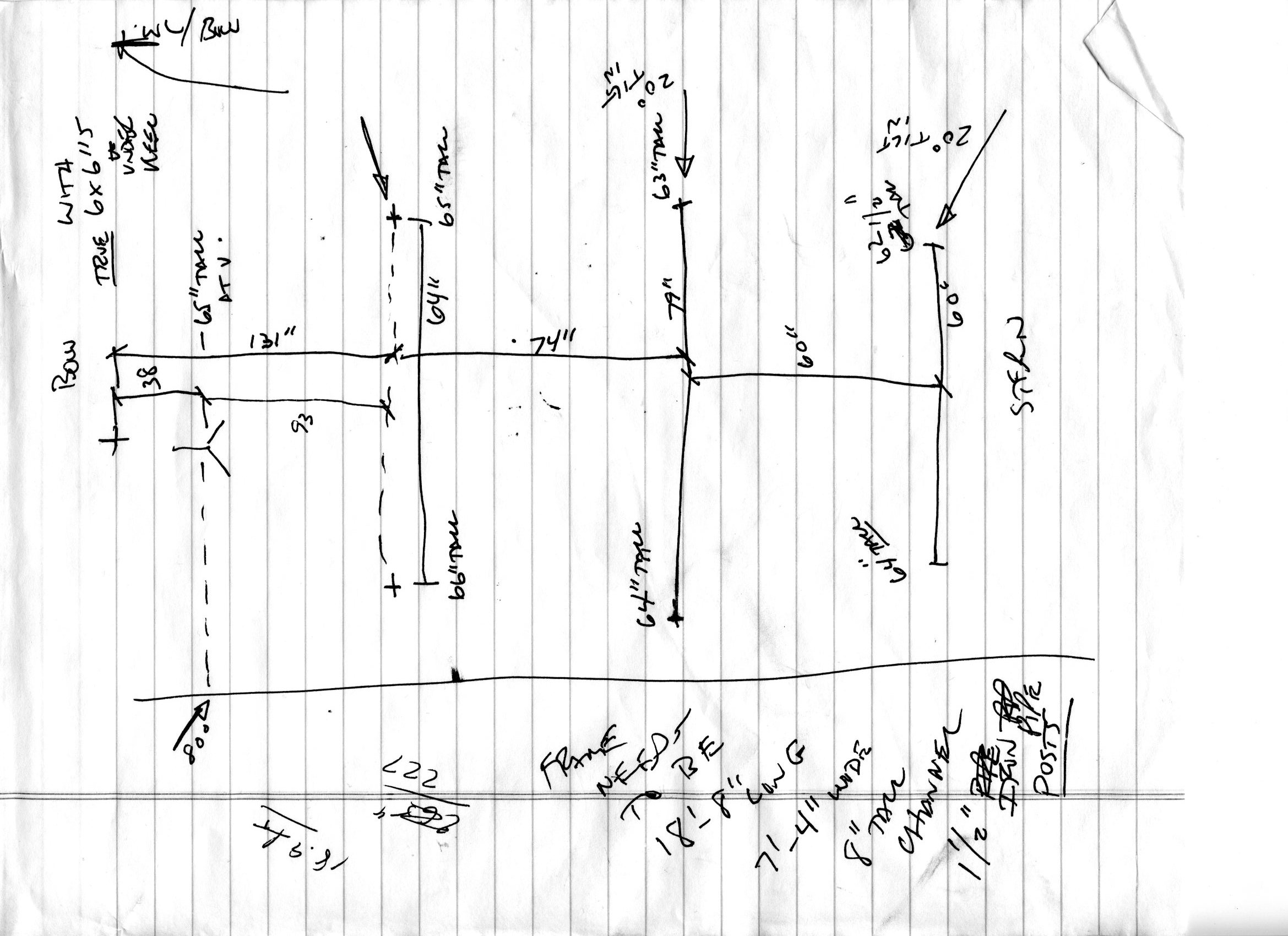
Before I launched the boat in 2014 I used a plumb bob, an inclinometer (Harbor Freight), a few long tape measures and some boards (for use as straight edges) to determine the location and angles of the existing stands which were holding the boat securely. The boat was supported by 7 stands. Three on each side plus a bow Vee stand. I referenced the port/starboard measurements off the centerline of the boat, and for a fore/aft location reference, I used the point that is formed between the centerline of the boat and the waterline of the boat at the bow. From these references I measured to the center of contact point for each stand support pad. (You have to visualize where that point is and make an educated guess since the reference point for the pad is actually at the pad/hull surface.) I also measured from the ground up to these pad contact points. In this situation, the boat's keel was sitting on several 6x6 wood blocks that actually measured 6" square. So putting all of this together resulted in 7 support locations in 3D space over the framework (which was already welded). Keep in mind that you need to be able to get travelift or crane straps under the boat while the supports are still in place.
Here you can see my hand written notes when I sketched the locations of the support pads in relation to the centerline of the boat and the front reference point on the bow.

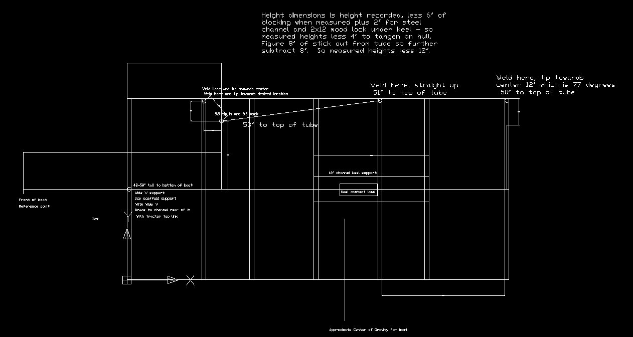
With this used cradle base that I purchased, I got lucky as I had support steel in the base where I needed it so I could attach the stands uprights. The rear two pads were shown in the drawing as being placed tilted in from the side but when doing the welding I also decided to tip them forward slightly. While that didn't hurt anything, I tipped them towards the front further than I should have by a few degrees.
Here is a shot of the working drawing I used to place the uprights.

For the new vertical support tubes, I purchased some seamless structural 1 1/2" OD tubing from a local steel surplus yard. It is surprising how much steel tubing is used for the uprights and then the diagonal supports for the uprights. I believe I used about 60 feet of steel tubing. I reused the pads and screws that came with the used frame.
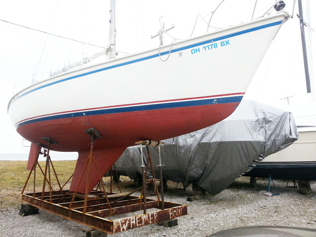
For the bow I decided not to use a Vee type stand top. I decided to go with a ladder type support and use two laminated 2x6 southern yellow pine boards as cross members that was carpeted to give the bow better support. With the swept keel, there is a lot of weight on the forward boat support stands and I was concerned that a V type stand there would have to much point contact pressure and possibly damage the boat. The flat 2x6 (times 2) beam covered with carpet distributes the load better. The ladder support moves up and down via two scaffold jacks. Scaffold jack feet are bolted to the 2x6's which are laminated together with epoxy and the scaffold jack screws fit into the vertical "ladder" members. A cross member stabilizes the "ladder" and fore-aft support is via a diagonal steel pipe that clips over the ladder cross member and attaches to the crossbeam in the base. The ladder support sits on short steel pins that are welded to the top of the 8" channel. In this way, the entire ladder support can be lifted off the base so the boat keel can be slid in between the uprights with the travelift without lifting the boat over the front bow support. The travelift operators seems to really appreciate this feature.
Here is a picture of the boat in the cradle. As you can see it still needs a paint job which will have to wait for warmer weather.
